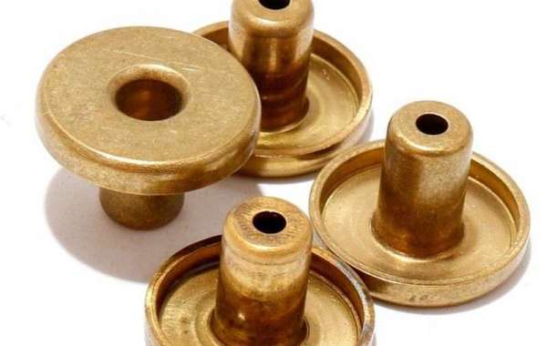
The measuring tool is responsible for carrying out both of these responsibilities. Height gauges, ordinary depth gauges, feeler gauges, internal and external thread gauges, R gauges, percent Table, dial indicator, gauge block gauge, roughness control sample block, altimeter, projector, three-dimensional coordinate 3D, 2D, etc. are examples of measuring tools that are used frequently. Other measuring tools include:Calipers, both traditional and digital, as well as depth calipers, are also among the other measuring tools available.
1. The utilization of a number of different measuring instruments, including calipers
Calipers are the measuring tools that are used the most frequently on the processing site. Calipers can be used to determine the distance between two points. Calipers are a useful tool for taking measurements of a wide variety of dimensions, including the inner diameter, the outer diameter, the length, the width, the thickness, the level difference, the height, and the depth of objects that are processed by mechanical parts.02 millimeters and a resolution of 0.02 millimeters per pixel.
Vernier caliper: resolution 0.
2. Use the piece of clean white paper to wipe away any dirt or dust that may be present before using the micrometer. When the surface of the screw and the surface of the object being tuned are located in close proximity to one another CNC milling service, fine-tuning is preferable to coarse-tuning because it results in a more accurate adjustment. To achieve this, turn the fine-tuning knob in the opposite direction of the clock. Stop the machine as soon as you hear three consecutive clicks, clicks, and clicks so that you can read the information from the display screen or the scale. The measuring contact surface and the screw only make very light contact with the product at any given time when they are measuring plastic products. Employing a height gauge in the specific setting that has been described
The primary purpose of the height gauge is to measure the height, depth, flatness, verticality, concentricity, and coaxiality of a wide range of mechanical parts, in addition to surface vibration, tooth vibration, concentricity, and coaxiality. Additionally, the height gauge can measure surface vibration and tooth vibration. No looseness. Measurement of flatness: Once you have positioned the precision CNC part on the platform where you want it, the next step is to use a feeler gauge to measure the distance between the part and the platform.
The straightness of the part is measured by first positioning it on the platform, then rotating it for a week, and finally employing a feeler gauge to determine the distance that exists between the part and the platform. This procedure is used to ensure that the part is as accurate as possible. The operation that must be carried out in order to insert the plug gauge (pin).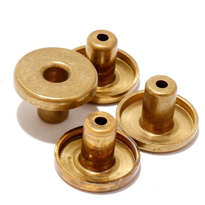 It is possible to obtain accurate readings for a variety of dimensions using it, including the inner diameter, the width of the grooves, and the clearance in the holes. If the hole diameter of the part is large and there is no needle gauge that is suitable for measuring it, the two plug gauges can be overlapping one another, and the plug gauge can be fixed on the magnetic V-shaped block according to the 360-degree direction. Device for accurate measurements of the two-dimensional variety that is used with the instrument
The second component is a non-contact measuring instrument that possesses both high levels of performance and precision. Because the sensing element of the measuring instrument is not in direct contact with the surface of the measured part, there is no mechanical action of the measuring force. This results in an inaccurate measurement. It can perform CAD output for 2D outline contours and measure a variety of geometric elements, such as distances, angles, intersections, and geometric CNC machining tolerances on the parts. Additionally, it can perform CAD output for 2D outline contours. In addition to that, it has the capability of measuring geometric tolerances. The software generates an image of it and displays it on the screen of the monitor attached to the computer.
Gate detection:There are frequently some gates that are concealed in the groove during the processing of molds; however, various testing instruments are unable to measure them due to the location of the gates. This is due to the fact that the groove is angled in a certain direction. Measuring device that focuses primarily on the third dimension as its primary focus
Can be utilized in the process of measuring geometric elements (in addition to the elements that are capable of being measured by the two-dimensional element, it is also capable of measuring cylinders and cones); Can be utilized in the process of determining the area of a geometric figure. A high level of precision (it can measure up to one meter), versatility (it can replace many different length measuring instruments), and portability are all features that come standard with this device. Can be utilized in the process of measuring geometric elements (as it can stand in for a variety of instruments that are utilized in the process of measuring length);Can be used for the purpose of determining the dimensions of various geometric components;Tolerances in terms of geometry (this includes cylindricity, flatness, line profile, surface profile, and coaxiality in addition to the geometric tolerance that can be measured by the two-dimensional element), as well as complex profiles, provided that a three-dimensional probe is used in the measurement process. Tolerances in terms of dimensions.
If there is a point on its surface that can be touched, then precise measurements of its geometric dimensions, mutual position, and surface profile can be obtained. When carrying out tasks that involve the processing of data, the utilization of a computer can be of great assistance. It is possible to measure not only the coordinate value of each component but also the contour of the uneven surface. This is possible even though 3d printing the surface is not perfectly flat.3D digital model import comparison measurement:A fit mold assembly needs to be performed when some of the surface contours are neither arcs nor parabolas but rather some irregular surfaces. This is done to verify that the finished parts are consistent with the design of the mold or to locate the fit abnormality that has occurred during the process. Because the value that is being measured is a point-to-point deviation value, it is easy to correct and can be improved, as well as done so in a timely and efficient manner. This is because the value that is being measured is a point-to-point deviation value. When it is not possible to perform the measurement of the geometric element, the 3D model can be imported. The parts can then be compared and measured in order to comprehend the processing error.